
This is my first DIY PICkit 2 clone. This simplified circuit from the original PICkit 2 circuit only support for 5v PICs.
Schematic
You can download the firmware from this link:
Program the firmware to your PIC18F2550:You can use free PIC programmer available on website to program your PIC18F2550. I use winpic800 version 3.61 and the programmer hardware art2003. Art2003 is a simple circuit and easy to make. The original art2003 designed to program PIC18F2550 on LVP ( Low-Voltage Programming ) mode. Which mean, LVP configuration bit must be enabled first. The new PICs have enabled LVP bit by factory settings. It's no problem for you to use the original art2003 to program the new PIC. You just need to enable the LVP bit every time you program your PIC to make sure that you can use the art2003 to reprogram your PIC on the future. Once, the LVP has been disabled, the PIC not working on art2003 anymore and you need to reprogram or enabling LVP bit by using High Voltage Programming mode. The disadvantage of enabled LVP bit is, the RB5 pin no longer can be use as an Input/Output pin. The RB5 must be pulled down to avoid the PIC entering LVP mode during running the PIC program. The problem here is, the PICkit 2 use the RB5 pin as an input pin, so, disabling LVP bit for the PIC18F2550 is needed.
Since, the art2003 just support for LVP mode. I modify the circuit so that it can support the High Voltage Programming. You also can use others hardware like JDM programmer or Propic2 to program the PICkit 2 firmware to your PIC18F2550 by using the winpic800.
Modified Art2003 Schematic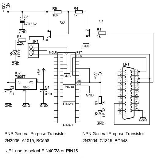

I edit the original firmware hexcode to get my own ID for my PICkit 2. You can see it on the pictures below

I just tried to construct a PICKIT2 using a solderless breadboard, but it didn't work. I still need to triple-check the wiring and such, but I may give this a shot. Right now, I'm only using PIC18f4550 anyway, (5v), so the target voltage shouldn't be much of a limitation. Thanks for listing!
ReplyDeletei have made this circuit but its not working may be its because of crystal.can you please tell me why crystal is not used in the circuit?and if it used then please tell me the value of it.please reply me soon.iam waiting.thanks
ReplyDeleteIm sorry, yes, im forgot to draw the crystal. Use 20Mhz
DeleteHi! Please, I assembled this circuit, but the pickit2 software gives a Vdd error, it says the device to be programmed already has a voltage, so it will disable Vdd. The problem is that I didn't even connect any PIC to be programmed, and there's no other voltage source! The software gives this error even when I don't connect anything to the pickit2. It seems the pickit2 is seeing a voltage generated by itself on pin 3. Any ideas on what may cause that? By the way, I don't have a BC327, I'm using a 2N3906, and I can also try the 2N2907. May this be the cause? Any sugestion? Thank you!
ReplyDeleteFound the problem, friend! I had to reduce C5 to 22nF, and mount it nearer the 5 pin header. I made the circuit in a very compact PCB (2.5cm x 5cm), and I think I had interference from the crystal or voltage pump affecting Vdd line. Now it works perfectly, thanks a lot!!
ReplyDeleteHi i have prepared my self to get into making this circuit's layout using eagle but how should i connect the ZIF socket to the programming outputs (VDD,VSS,CLK, PDAT) ??
ReplyDelete카지노사이트 카지노사이트 クイーンカジノ クイーンカジノ dafabet dafabet 카지노사이트 카지노사이트 10cric login 10cric login 853
ReplyDelete